The first important thing to know is that a size 1 grid in Max roughly corresponds to 1 foot in Thief. So first thing - set your grid spacing to 1. If you have a favorite layout that you're familiar with and wish to use, that's fine, but since I have no way of covering all the possible layouts, I will use Top, Front, Left, and Perspective. Another important thing to note (although it won't matter for this tutorial) is that in Max, the Left view = Front in Thief. For example: When I create a bottle with a label, I want the label to be facing front. When the player drops the bottle, I want it to land with the label facing him or her. The game engine is picky that way. So if you ever make objects that have a "front", make sure it's facing you in Max's Left viewport when you export it. On with the tut...
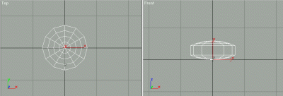
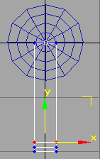
Zoom in on all your viewports until you see Grid = 1.0 on the toolbar. We're going to make a functional ceiling fan! Click on the "create" tab and select the "oil tank" button. Oh yes, by the way, I'm using Max R3 for this tutorial. Under the "parameters" section, type in 12 for the number of sides, and 1 for the height segments. Smooth should be checked. In the Top viewport, zoom in until you can only see about 4 grid squares. Put your mouse cursor in the zero point and click-drag to the right about 3/4 of 1 grid square, click again and drag about half a square, then double click, since we'll set the dimensions manually. On the Parameters rollout, type in Radius 0.7, Height 0.6, Cap Height 0.15 (If you don't see two decimal places, go to Customize>Preferences>General> and set Spinner precision to 2 decimals). Right-click in the active viewport and select Properties, and change the name from "OilTank1" to "aa", then click OK. You should now have something like this:
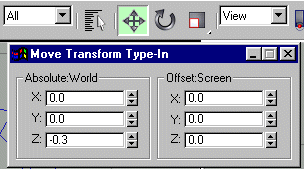
Now select your standard primitives (or Objects tab) and click on "cylinder". Set the sides to 8 in the rollout, height and cap segments to 1 (remember we're supposed to be low-polygon modelling). In the Top viewport again, create a cylinder from the center, click-drag until about the first "ring" of the oil tank, click and drag to give it a little height (we're going to refine this on the rollout). On the rollout, type in the following settings for the cylinder: radius = .04, Height = 1.3. With the cylinder still selected, click on the "Select and Move" icon, then right-click on it to bring up the Move Transform Type-in box. Type in -.3 for the Z axis in Absolute World. Now you should have something like this in the Front viewport:
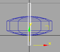
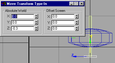
Now select a Box from your Standard Primitives, and on the rollout type in 1 for Length and Width segments, and 3 for height segments. In the Front viewport, click-drag about 1/8 of a grid to the left of center, just below your cylinder, to about the same amount to the right (try to get it centered on the bottom of your cylinder, but no need to be exact, as we'll type in again), then drag it just a little for the length. In the rollout, type in the following: Length = .05, Width = .4, Height = 2.0. With the box still selected, go back to your Move Transform Type-in and under Absolute World type in X = 0.0, Y = 0.0, Z = -.3 (remember, -.3 is where we set the bottom of the cylinder). So now you should have something like this:
With your box still selected, select "edit mesh" from the Modify panel. Click on the Vertex sub-object on the rollout. Select your Move tool, and in the Top viewport drag a box around the set of vertices closest to the bottom edge of your box. Move them on the Y axis until they are about 1/8 of a grid away from the end of the box. Then do the same for the other middle set of vertices, like so:
Now zoom in fairly close in the Front viewport, so you can watch what's happening. Go back to the Top viewport and zoom in close to the tip of the box. Drag a selection box around the end set of vertices. Select your Scale tool, click-drag to scale the vertices down to about 1/2 of their original dimensions (we're forming the tip of the fan blade). Drag a box around the next set of vertices and click-drag to scale them down to about 3/4 of their original dimensions. Select your Move tool, an drag the sets of vertices into a position that looks good, like so:
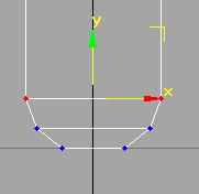
You should have noticed in the Front viewport that scaling down also made the tip of the blade narrower vertically. This will give the blade a nice shape. Still in the Top viewport, move upward to the other end of the box, at the center point. With your Move tool, select one set of corner vertices and move them on the X axis toward the center, about halfway between your cylinder and the first ring of your oil tank. Ditto for the other corner vertices, like so:
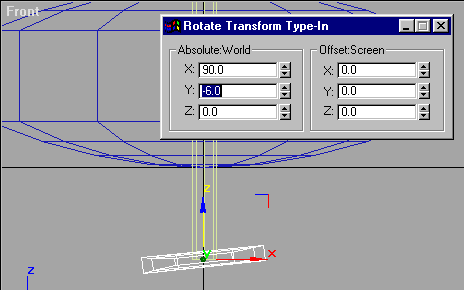
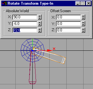
Now de-select Sub-object and go to the Front viewport. Select the Rotate tool, then right-click on the rotate tool icon to bring up the Rotate Transform Type-in box. Absolute World, type in -6.0 for the Y axis (X should already be 90). So now you should have this:
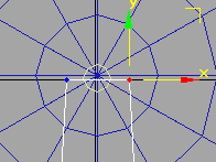
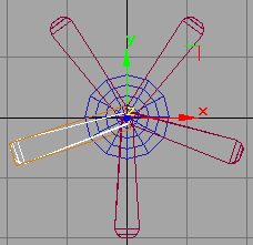
Go back to your Top viewport and zoom out a little until you can see just over 4 grids top-to-bottom. With your fan blade still selected, on the Modify panel click on UVW Map, and select Box on the Mapping rollout. It should automatically shape itself to the correct dimensions. Now bring up the Material Editor. Expand the Maps rollout, and click on the button labeled "none" next to Diffuse Color. Double-click Bitmap at the top of the resulting list, and browse to your unzipped obj.crf folder. In sub-folder obj/txt16 find "Wintrim.gif" and select it. Click on the "Assign Material to Selection" button in Material Editor. We're doing this now because it will save us from UVW mapping and assigning materials separately for all the blades. Since we'll clone this one that's already mapped/textured. Close the Material Editor. With your box still selected, and the Top viewport active, select Edit>Clone>Copy. Now select, then right-click your Rotate Tool icon. In the Rotate Transform Type-in, Absolute World, type in 72 in the Z axis. You should now have this:
Leave the Rotate Transform Type-In box on your screen and go back to Edit>Clone>Copy, then type in 72 on the Z axis in Offset: Screen. Do this two more times until you have this:
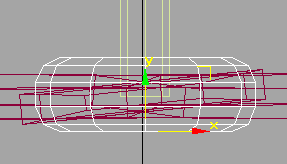
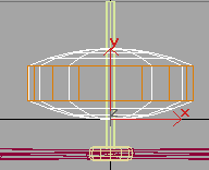
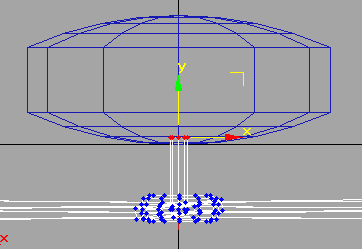
Now we need to make a hub for our fan blades. Select a chamfer cylinder from the extended primitives, and set the following on the rollout: Height Segs = 1, Fillet Segs = 2, Sides = 12, Cap Segs = 1. Zoom in close to the center in the Top viewport and click-drag from the zero point out to the first ring of your oil tank. Click, drag a little, click again. On the rollout, type in the following: Radius = .18, Height = .12, Fillet = .04. Now select your Move tool, and in the Front viewport drag your chamfer cylinder down on the Y axis until it's centered on the fan blades, like this:
That should make a decent hub. With the chamfer cylinder still selected, click on UVW Map, leaving it Planar (BTW: Paint Shop Pro comes in handy for this. Its "browse" feature is indispensable when sorting through lots of textures). Bring up the Material Editor and click on an empty sample box. Maps rollout>Diffuse Color>Bitmap> browse to "Gasball2.gif" and select it, then apply material to selection (another tip: it saves file size, mission size, etc. if you can sometimes use textures that are already in the game, since there's no need to distribute them with your objects). Select your oil tank and UVW Map, selecting Cylindrical on the rollout. Looking in your Front viewport, use the Height spinner on the UVW Map rollout to adjust the height of the UVW Map until it's the same height as the center section of the oil tank, like so:
Material Editor>Maps rollout>diffuse color>bitmap> browse to "Gearpat1.gif", select, and apply material to selection. If you do a quick render now you'll see that the oil tank looks pretty bad. On the UVW Mapping rollout, type in 4.0 for the U Tile parameter, which should look like this now:
Select your first cylinder, that long skinny one, and UVW Map, Cylindrical. Get and apply the material named "Bronz6.gif" for the cylinder. That's everything as far as texturing goes. Now we need to tell the game where the central axis of the fan blades is, so it knows where to rotate it from. An "axle" in Thief is simply a straight line connecting two points which is perpendicular to the face of the rotating object (think of it in terms of a spinning top, and an imaginary line from the top to bottom, going straight down through the center, or the metal bar inside the middle of a Yo-Yo). So go to the Front viewport. On your Create menu, select, Splines > Line. Zoom in very close in the Front viewport (you may want to use the Min/Max Toggle to go into single-viewport mode for this). The length of the line is really arbitrary, as long as it's a straight line, so click about an inch above the top of the chamfer cylinder that we're using for a hub, drag the line to about an inch below the bottom of the hub, click again, then, without moving the mouse, right-click to end the line with just two points. With the line still selected, select then right-click on the Move Icon, and in the Move Transform Type-In, Absolute World, type in 0 for both the X and Y axis (type it in even if it's already zero. Unless you have Max configured to show lots of decimals, it may say zero and still be off-center). With the line still selected, right-click on the screen and select Properties, and rename it from "Line1" to "@x00aa2500". This is the Thief terminology for an axle. X = rotating (if it was translating we would use a "z"), 00 = axle number zero (you can have more than one axle, starting with zero), aa = name of parent object, 2500 = ?? I have no idea. I've seen many varied numbers in Thief objects, anything from 1010, 9999, 10000, 2500, etc... Though some people say they know what this means, I don't think anyone has positive proof of what it does. The majority of Thief moving objects use 2500, so we'll stick with what works.
You may have noticed that your cylinder is a bit off-center (mine was). Using the Move Transform Type-In didn't get it to the centerpoint either. We need to make sure everything is centered exactly, otherwise we'll have lopsided rotation when the fan is spinning. Select the cylinder, then click on the Heirarchy Panel. Select "Affect Pivot Only", then click "Center to Object". De-select "Affect Pivot Only", then in the Move Transform Type-In set the X and Y axis to zero. IMPORTANT! Once you center an object, be absolutely sure to go to the Heirarchy > Affect Pivot Only > Reset Pivot! I learned the hard way that somehow, the pivot point for an object is created "at birth", and recorded somewhere. If you don't reset the pivot to its original state, really funky things can happen in the game. I've seen robots flying apart, objects rotating way off-center, you name it! Even if you (and me!) think that a pivot should be "centered to object, it just doesn't work that way. So a good rule of thumb before exporting is to "select all" > Heirarchy > Affect Pivot Only > Reset Pivot.
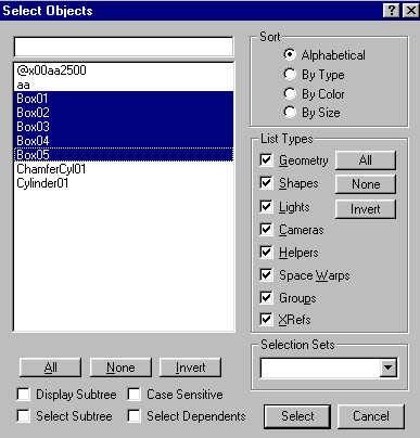
If your oil tank or anything else looks off-center when viewed close-up in the Top/Front/or Left viewport, center them now. Save as whatever.max. Click the "Select by Name" icon and select Box01 thru Box05.
One of the vagaries of Thief: It doesn't allow multiple parts to an object that has moving parts. You can only have a base object, axle(s), and sub-object(s), so we'll need to condense here. On the Utilities panel, select Collapse, then "Collapse selected". This will make the 5 fan blades into one object, but won't mess up their UVW mapping. However, we can't collapse with the hub, because it has a different material. Now all 5 fan blades should be one object, and still selected. Right-click in the active viewport and select Properties, and change the name from "Box0x" to "@s00bb". In Thief terminology, s = sub-object, 00 = sub-object number zero, bb = name of sub-object. Now go back to the Modify panel and you'll see that the collapsed fan blades don't show UVW Mapping anymore, and instead are listed as an editable mesh. You should always save before doing a collapse or an attach, just in case something goes wrong. On the Modify panel rollout, click the "Attach" button, then click on the chamfer cylinder that's our "hub". A box should pop up with some options on material matching. Select "Match material ID's to material". If you do a quick render in the perspective viewport of the bottom of the fan, you should see that the hub retained the metal material, while the fan blades are still wood. With the attach button still active (or if not, click it again), click on the cylinder that runs up through the oil tank. Again, match material ID's to material.
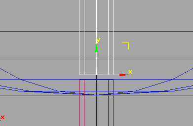
I decided about halfway through this tutorial that I wanted the shaft to rotate also, not just the blades and hub. But there's a hitch...the shaft rotating below the oil tank is fine, but the part that's supposed to connect to the ceiling shouldn't rotate. De-select the attach button and select the Vertex sub-object. In the Front viewport, drag a box around all the vertices at the very top of the cylinder, then use the Move tool to move them downward on the Y axis until they're just inside the oil tank, like so:
Now we need another cylinder to hang this thing by. Go into the Top viewport and select cylinder from your Standard Primitives. Set the Sides to 8 and Height Segments to 1 on the rollout. Click-drag like you made the first cylinder. Max may be finicky about creating a very small diameter cylinder, so just make a bigger one if you have to. On the rollout, set the Height to 0.8, and the radius to .04. Select the Move tool icon and right-click, and type in all zero's for the Absolute World coordinates (even if they're already zeros!). In the Top viewport, you should see that the new cylinder is perfectly aligned with the original. With the move tool still selected, in the Front viewport, move the cylinder up a little on the Y axis, so the bottom of it is just above the other one, like so:
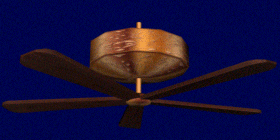
UVW Map it, switch it to Cylindrical on the rollout, and apply your "bronz6.gif" from the Material Editor. Select the oil tank (which is now named "aa"), go to the Utilities panel and collapse it. Go back to the Modify panel and select "attach", then click on the new cylinder, and select match material ID's to material. Click on the "select by name" icon and you should see "aa", "@x00aa2500", and "@s00bb". If not, then something went wrong. The fan blade assembly should be named "@s00bb", the Line should be "@x00aa2500", and the oil tank/cylinder combo should be "aa". A quick-render should show everything is in order:
Still with me? Everything work OK? :) One more thing before we're done with Max and ready to take this thing to Dromed. Objects should always be centered as much as possible to the absolute zero point of the world. When Dromed loads an object, it bases the center of the object on the world zero axis, so...let's say you build a tall tower, like my windmill, and it's resting its base on the zero point. You export it and bring it into Dromed, and (assuming the object is 20 units tall), the "bounding box" you see in Dromed is going to show that you need to place it halfway underground for it to sit on the ground! ie: The center of the bounding box is always the zero point of the world axis, so you'd need exactly half of your object below the coordinates 0,0,0. So...easy to rectify. Select ALL. Click the Move icon and right-click for the Transform Type-in. Hmm...no coordinates in the Absolute World??? ;) Select Group>Group, click OK on the default name. Now type in 0,0,0 in the Absolute World coordinates to center the mass on world center, then Group>Ungroup. Ta da! File > Export > 3D Studio (.3ds), preserve Max's texture coordinates.
Now, I hope you have N3ds2e.exe! If not, grab it from my site here. Browse with Windows Explorer to where you exported the file, and be sure you have N3ds2e.exe in the same folder. I suggest getting "command prompt here" from Microsoft's website if you're running a version of Windows that supports it. Makes things alot easier. If not, you'll need to go to Start>Run>Command (or the shortcut to the DOS prompt in System Tools folder, or whatever works on your machine). Type: n3ds2e filename.3ds to convert it (I personally made a .bat file so I just have to type "3e filename". You'll need bsp.exe, which came on the Thief 2 CD. It may be zipped up somewhere, I don't recall. Anyway, type "bsp filename.e and don't worry if you see alot of atomic warnings. ;) Close the DOS prompt, and in Explorer cut your new .bin file and paste it into your Thief2/obj folder. Fire up Dromed, click on Editors>Object Heirarchy>Physical>Gizmo>Electrics>Turbines>Turbine. Highlight "turbine" and click the ADD button. Type in any name you desire. Click OK, then double-click the new name. Click ADD>Shape>Model Name. Type in the exact name of your fan (minus the .bin part). Click Done. Click Create. Make it, portalize....Alt+G and go see it working!
Tweaking: This all depends on the type of object you made and where it fits into Dromed the best and easiest. In this case, I added it under the turbine because I knew that the turbine had a constantly rotating sub-object. If I was putting this in a mission, I'd do the following: With the new fan you just created selected in Dromed, click on "properties" down by the bottom of the screen. Open the Physics>Model subtree. Double-click "dimensions". I know from the grid size in Max that this fan is about 4,4,1.2 in the X,Y, and Z respectively. What if you wanted to change the speed or direction of rotation? Click ADD>Tweq>Joints. It has inherited the turbine's settings, so you'll see "continue" in the top box, which tells the game to make the fan rotate non-stop. And AnimC is set to "no limit". The primary joint is 1, which was our @x00aa2500 joint. You can have more than one axle. Rate-Low-High: Rate is the rotational speed. Change this to a low number for a slower-turning fan, higher for faster. The Y and Z values determine how many degrees the sub-object will rotate on that axis. In our case, we don't want (and can't have) and movement in the Y axis, which is for levers and other translating objects, and we want 360 degrees of rotation on the Z axis.
Well, that concludes this tutorial. A last note: Making a translating object is much the same. You just use "Z" instead of "X" in the axle name (ie: @z00aa2500). Make a base object, a moving part like a lever, and the line for the axle. Create it in the Object Heirarchy under another translating object, such as the BigFloorLever or Mech Antenna Switch. You get the idea. Of course that involves frobbing and other things that are beyond the scope of this tutorial. :) I hope it worked for you! Feel free to e-mail me if you have any questions or comments.